Monday, October 31, 2016


Wednesday, October 12, 2016
Saturday, March 16, 2013
CGS Head Rig Animation
Hey everyone! I want to share my latest animation. I rigged the head over several weeks and animated it in the past few days. I haven't worked on any corrective blends yet so I'm still open to critiques. The animation is meant to push the limits of the rig. Thanks for watching!
Wednesday, March 13, 2013
Angle Based Deformers
What I am about to talk about is closely related to Pose Space Deformers--I’m sure you can find the original SIGGRAPH PSD papers online. However, the setup I present below is a simple network that allows you to trigger actions and/or blends based on the angle between two vectors. Vectors save the day once again…
Why ditch Euler angles when we already have angle positions?? Because of the nature of Eulers, the X, Y, and Z components are calculated in a specific way that won’t work in many situations. One of the main reasons for this is Gimbal Lock. This one reason can make things a living nightmare for us.
Using the dot product, we can find the angle between two vectors, A and B, by using the following equation:
Θ = acos(A · B)
This means that if we were to attach a locator to a pair of adjacent joints, where both locator’s origin is positioned where the joints connect, you can find the arc cosine of the dot product of both of these vectors, and return the angle between them. I know… it sounds wordier than it really is.
Here’s how I set this up in Maya:
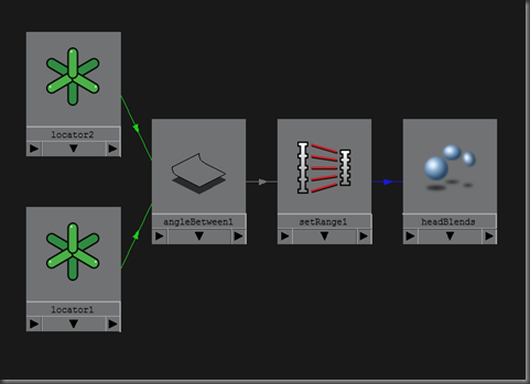
To be able to see the results of my network, I attached the output of setRange to a blendshape channel. I then animated the joint driving the location of a locator to get a change in the angle between locator1 and locator2. Maya’s angleBetween node returns 0-180, so I scaled that value down to 0 to 1 using the setRange node.
We could have just as easily used an expression to put this example together. However, I prefer to stay away from expressions for anything that I can build using nodes. Native nodes evaluate faster and you can’t break their dependencies by duplicating the network or changing their names!
I hope you can find many uses for this angle based setup. Let me know what you come up with!
Why ditch Euler angles when we already have angle positions?? Because of the nature of Eulers, the X, Y, and Z components are calculated in a specific way that won’t work in many situations. One of the main reasons for this is Gimbal Lock. This one reason can make things a living nightmare for us.
Using the dot product, we can find the angle between two vectors, A and B, by using the following equation:
Θ = acos(A · B)
This means that if we were to attach a locator to a pair of adjacent joints, where both locator’s origin is positioned where the joints connect, you can find the arc cosine of the dot product of both of these vectors, and return the angle between them. I know… it sounds wordier than it really is.
Here’s how I set this up in Maya:

To be able to see the results of my network, I attached the output of setRange to a blendshape channel. I then animated the joint driving the location of a locator to get a change in the angle between locator1 and locator2. Maya’s angleBetween node returns 0-180, so I scaled that value down to 0 to 1 using the setRange node.
We could have just as easily used an expression to put this example together. However, I prefer to stay away from expressions for anything that I can build using nodes. Native nodes evaluate faster and you can’t break their dependencies by duplicating the network or changing their names!
I hope you can find many uses for this angle based setup. Let me know what you come up with!
Saturday, February 9, 2013
NURBS Curves: How to use Knot Vectors
When working in Maya, we create curves freely without crunching numbers. We use them in Maya Hair, Spline IK rigs, Motion/Flow paths, as control curves for characters rigs, create them procedurally for modeling, amongst other uses. My goal in this post is for you to better understand how to generate curves using knot vectors.
Linear curves are simply lines that follow the standard y = mx + b formula. In Maya, they are created as a curve of 1 degree. That means that the highest power in the equation is 1. In theory, this curve type has 2 knots. The relation between knots to CV is: #knots = (#CVs+deg -1).
string $curve = `curve -d 1 -p -2 0 0 -p 2 0 -2`;
Simply pass in your two points, and tell Maya that you’re drawing a linear curve. Let’s attach a curveInfo node to this curve and poke around a little bit.
string $cInfo = `arclen -ch 1 $curve`;
getAttr($cInfo+".knots[*]");
// Result: 0 1 //
It seems that there are two knots on this curve that are weighted to each CV on the curve. Using #knots = (#CVs+deg -1), we know that we have 2 CVs on a curve of 1 degree, minus 1: that’s 2 knots. So we know that checks out.
Before we investigate further, let’s try the same thing with a quadratic curve. Behind the scenes, Maya will draw the smooth curve using an equation where the highest degree order is 2. Since we all miss our high school math classes, let’s draw a parabola:
$curve = `curve -d 2 -p -1 0 -2 -p -1 0 0 -p 1 0 0 -p 1 0 -2`;
$cInfo = `arclen -ch 1 $curve`;
getAttr($cInfo+".knots[*]");
// Result: 0 0 1 2 2 //
We have a curve of 2 degrees, we plotted 4 points, minus 1: that’s a total of 5 knots. The collection of knots on a curve is referred to its Knot Vector. However, what do these knot magnitudes mean? Each element in the vector determines where in parameter space the curve will be drawn. I know that’s a very vague statement but please stay with me!
Think of the first and last points on a curve as an anchor. This is the most common type of knot vector: Pinned Uniform Knot Vectors. Each anchor needs to be held down by the same number of knots as the curve’s degree. In our first example, we had a curve of 1 degree being pinned down by one knot on each end point. In our second example, we had a curve being held down by 2 knots on each end point.
So then what does the 1 mean in the [0 0 1 2 2] result? It turns out that these numbers are arbitrary. The number values don’t matter in a Knot Vector. Say what? Yes, that’s right. What matters is the ratios of the values to each other. The main rule is that Maya requires each knot’s magnitude to be in ascending order. So what happens if we create a curve but mess with that middle knot? What results will we get? Let’s try it!
Just for fun, we can weight the center knot to the other end to get a mirrored result.
Uniformly distributing our knots makes our NURBS curve simply a B-Spline. Having the ability to specify and interactively adjust the knots is a feature of NURBS, or Non-Uniform Rational B-Splines. Allowing a partial knot weight is a nice feature:
Linear curves are simply lines that follow the standard y = mx + b formula. In Maya, they are created as a curve of 1 degree. That means that the highest power in the equation is 1. In theory, this curve type has 2 knots. The relation between knots to CV is: #knots = (#CVs+deg -1).
string $curve = `curve -d 1 -p -2 0 0 -p 2 0 -2`;
Simply pass in your two points, and tell Maya that you’re drawing a linear curve. Let’s attach a curveInfo node to this curve and poke around a little bit.
string $cInfo = `arclen -ch 1 $curve`;
getAttr($cInfo+".knots[*]");
// Result: 0 1 //
It seems that there are two knots on this curve that are weighted to each CV on the curve. Using #knots = (#CVs+deg -1), we know that we have 2 CVs on a curve of 1 degree, minus 1: that’s 2 knots. So we know that checks out.
Before we investigate further, let’s try the same thing with a quadratic curve. Behind the scenes, Maya will draw the smooth curve using an equation where the highest degree order is 2. Since we all miss our high school math classes, let’s draw a parabola:
$curve = `curve -d 2 -p -1 0 -2 -p -1 0 0 -p 1 0 0 -p 1 0 -2`;
$cInfo = `arclen -ch 1 $curve`;
getAttr($cInfo+".knots[*]");
// Result: 0 0 1 2 2 //
We have a curve of 2 degrees, we plotted 4 points, minus 1: that’s a total of 5 knots. The collection of knots on a curve is referred to its Knot Vector. However, what do these knot magnitudes mean? Each element in the vector determines where in parameter space the curve will be drawn. I know that’s a very vague statement but please stay with me!
Think of the first and last points on a curve as an anchor. This is the most common type of knot vector: Pinned Uniform Knot Vectors. Each anchor needs to be held down by the same number of knots as the curve’s degree. In our first example, we had a curve of 1 degree being pinned down by one knot on each end point. In our second example, we had a curve being held down by 2 knots on each end point.
So then what does the 1 mean in the [0 0 1 2 2] result? It turns out that these numbers are arbitrary. The number values don’t matter in a Knot Vector. Say what? Yes, that’s right. What matters is the ratios of the values to each other. The main rule is that Maya requires each knot’s magnitude to be in ascending order. So what happens if we create a curve but mess with that middle knot? What results will we get? Let’s try it!
curve -d 2 -p -1 0 -2 -p -1 0 0 -p 1 0 0 -p 1 0 –2By specifying the knot values to the curve command, it seems we have created a curve with non-uniform weighting. We modified the middle knot in a way that we made the curve appear discontinuous.
-k 0 -k 0 -k 0 -k 2 -k 2;
Just for fun, we can weight the center knot to the other end to get a mirrored result.
curve -d 2 -p -1 0 -2 -p -1 0 0 -p 1 0 0 -p 1 0 –2Go ahead and release the pins on this 2nd degree curve. Notice that you can easily un-anchor the curve from their start and end points by simply supplying different weights. This also makes your curve a lot shorter. This is something you need to try for yourself because it’s one of those things that are too abstract in words.
-k 0 -k 0 -k 2 -k 2 -k 2;
Uniformly distributing our knots makes our NURBS curve simply a B-Spline. Having the ability to specify and interactively adjust the knots is a feature of NURBS, or Non-Uniform Rational B-Splines. Allowing a partial knot weight is a nice feature:
curve -d 2 -p -1 0 -2 -p -1 0 0 -p 1 0 0 -p 1 0 –2Finally, to nail the point, let’s try drawing an pinned cubic curve with a degree of 3.
-k 0 -k 0 -k 1.5 -k 2 -k 2;
curve -d 2 -p -1 0 -2 -p -1 0 0 -p 1 0 0 -p 1 0 –2
-k 0 -k 0 -k 0.5 -k 2 -k 2;
curve -d 3 -p -1 0 -3 -p -2 0 -2 -p 0 0 0 -p 2 0 -2 -p 1 0 –3Notice that I used 3 pinned knots to hold down the end points. The middle knot is exactly half way between 0 and 2. This makes the curve uniformly weighted. If you have questions, please let me know in the comment section! I’m sure there are things I can clarify. I want to be sure the information comes through clearly.
-k 0 -k 0 -k 0 -k 1 -k 2 -k 2 -k 2;
Notes:
- Maya seems to ignore knot magnitudes on linear curves.
- When creating curves with the -pointWeight flag, accurate knot values are not returned.
- When editing curves created with the -pointWeight flag in the viewport, the curves seem to snap to a weighted value of 1 to each CV.
Wednesday, February 6, 2013
A List of My Favorite Books
Several people have asked me about what resources I use to learn my favorite topics. There are informative videos and written tutorials scattered all over the web, and only but a few are concise, efficient, and well prepared. This is why I rely mostly on books that are written by seasoned professionals that know a thing or two about teaching. Here is a list of the books I am in love with:
These gems are not listed in any particular order but MEL Scripting for Maya Animators was the first book I ever read on MEL, or Maya for that matter. I bought the very first edition of that text because I was looking for a source of inspiration when I was stuck at home writing Game Development with ActionScript. They are both considered oldies as far as technology goes, so they might be tough to find.
- MEL Scripting for Maya Animators
- Mastering Autodesk Maya
- Stop Staring: Facial Modeling and Animation Done Right
- Maya Python for Games and Film
- Complete Maya Programming I & II
- Art of Rigging I & II
- Professional MEL Solutions for Production
- Maya Visual Effects: The Innovator's Guide
- 3D Math Primer for Graphics and Game Development
- Game Development with ActionScript
These gems are not listed in any particular order but MEL Scripting for Maya Animators was the first book I ever read on MEL, or Maya for that matter. I bought the very first edition of that text because I was looking for a source of inspiration when I was stuck at home writing Game Development with ActionScript. They are both considered oldies as far as technology goes, so they might be tough to find.
Saturday, February 2, 2013
Understanding 3D Vectors
DISCLAIMER: This post covers the vector type in Maya. If you are new to vectors, please acquaint yourself with them and review the help docs before reading this post. I tried to keep this post as light on math as possible, however, I will clarify where needed, based on your suggestions. This is a huge topic and this post merely summarizes how useful vectors are.
User Guide > Scripting > MEL and Expressions > Useful functions
Let’s break one of our toys apart and learn how things work from the inside out. The knowledge we acquire from doing this allows us to build bigger and better toys. In physics, a vector is described as an entity that has both a magnitude and a direction. In MEL, a vector is represented by x, y, and z components. These components can be combined back into their scientific form at any time. Vectors can represent a location in space, the velocity and/or acceleration of an object, tracing rays between two points, etc.
Retrieving a vector’s magnitude is trivial in MEL:
vector $A = << 1, 2, 3>>;
vector $B = << 3, 2, 1>>;
int $length = mag($A);
Finding the direction vector can by done by using the unit function.
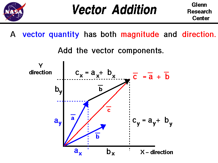
 When you perform arithmetic with vectors, the output is considered the resultant. Addition yields a vector that is said to be a diagonal in a parallelogram.
This is interesting to us because if you were to take the B and move a copy (by adding it to A) to the head of A, we build ourselves a triangle that can used to solve for solutions. If we then move a copy of A to the head of B, we end up with a parallelogram. When you subtract a vector from another, the resultant yields a magnitude that is the distance between the heads of A and B. If you take B-A (, which is not the same as A-B, ) and add it to A, we have ourselves another triangle. Still with me? This is only possible because a vector can be equal (& parallel) to any other vector in space as long as they are equal in direction and magnitude. So if you need to reposition a vector, do so by adding it to another vector location. That was the heaviest paragraph in this post, I promise!

By multiplying a vector by a scalar value, we are simply scaling the the vector’s magnitude by that number. There are other types of vector products that are extremely important in computer graphics, the dot product, which yields a scalar value, and the cross product (, which yields another vector perpendicular to the first two. Nuff talk, let’s get to work.
In Maya, create 4 locators. Name them A, B, C, & D. In the script editor, retrieve their world space positions and store those values in vectors. Imagine each locator to be a ray, that originates at the origin, and each locator shape being the vector’s head. Spread the locators in space away from the origin and each other, arbitrarily and for variety.
Make C perpendicular to the first two, by taking the cross product of A & B and move C to the resultant. Now that you know that C perpendicular to the first two, there’s a good chance there is one axis that is not perpendicular to another. You can verify this by taking the dot product of two vectors. If the dot product is not 0, then your vectors are not perpendicular.
TIP: Make the result of AxC a unit vector, a vector with the length 1, by using the unit function on C. The 'x' in this notation signifies we're taking the cross product of these two vectors.
Anyway, take the cross product of A & C, and feed the result to B. You now have 3 axis that are perfectly orthogonal to each other. Assuming that A was already at the “lookAt” location, let’s place D along A’s axis, but with a magnitude of 1. Vectors of this length are called unit vectors. The process of getting this result is call normalization.
Normalize A and pipe the results right into D. You now have solved for the same things that the aim constraint solves for in most 3D software, including games. If you were to normalize all 3 orthogonal axes, you would have what is called an Orthonormal Basis.
Here's a code snippet:
// 3D (Basis) Vectors
// By Lewis M., 2013
// Usage:
// Arbitrarily place four locators in the scene
// Name them A, B, C, & D
// Retrieve A & B's locations
float $a_coord[] = `xform -q -ws -t A`;
float $b_coord[] = `xform -q -ws -t B`;
// Find an orthogonal vector to both A & B
vector $a = <<$a_coord[0], $a_coord[1], $a_coord[2]>>;
vector $b = <<$b_coord[0], $b_coord[1], $b_coord[2]>>;
vector $c = cross($a, $b);
vector $d;
// Scale it down to the length of 1
$c = unit($c);
move -a ($c.x) ($c.y) ($c.z) C;
print dot($a, $b); // Most likely not zero
// Adjust B to be orthogonal to both A and C
$b = cross($a, $c);
$b = unit($b);
move -a ($b.x) ($b.y) ($b.z) B;
// Finally, scale down A and place D in the position
$d = unit($a);
move -a ($d.x) ($d.y) ($d.z) D;
// Just for fun, draw some visually appealing curves
curve -d 1 -p 0 0 0 -p ($a.x) ($a.y) ($a.z) -k 0 -k 1 ;
curve -d 1 -p 0 0 0 -p ($b.x) ($b.y) ($b.z) -k 0 -k 1 ;
curve -d 1 -p 0 0 0 -p ($c.x) ($c.y) ($c.z) -k 0 -k 1 ;
//grid -tgl 0;
//refresh;
As an exercise, you can use MEL, Python, or even utility nodes to create the connections.

Above is a picture of my little aim constraint node setup. It differs from my discussion above because this version is interactive. In this version, I am able to position A wherever I want and have the other locators automatically update. The NURBS curves you see there are strictly for visual appeal
User Guide > Scripting > MEL and Expressions > Useful functions
Let’s break one of our toys apart and learn how things work from the inside out. The knowledge we acquire from doing this allows us to build bigger and better toys. In physics, a vector is described as an entity that has both a magnitude and a direction. In MEL, a vector is represented by x, y, and z components. These components can be combined back into their scientific form at any time. Vectors can represent a location in space, the velocity and/or acceleration of an object, tracing rays between two points, etc.
Retrieving a vector’s magnitude is trivial in MEL:
vector $A = << 1, 2, 3>>;
vector $B = << 3, 2, 1>>;
int $length = mag($A);
Finding the direction vector can by done by using the unit function.

This is interesting to us because if you were to take the B and move a copy (by adding it to A) to the head of A, we build ourselves a triangle that can used to solve for solutions. If we then move a copy of A to the head of B, we end up with a parallelogram. When you subtract a vector from another, the resultant yields a magnitude that is the distance between the heads of A and B. If you take B-A (, which is not the same as A-B, ) and add it to A, we have ourselves another triangle. Still with me? This is only possible because a vector can be equal (& parallel) to any other vector in space as long as they are equal in direction and magnitude. So if you need to reposition a vector, do so by adding it to another vector location. That was the heaviest paragraph in this post, I promise!
By multiplying a vector by a scalar value, we are simply scaling the the vector’s magnitude by that number. There are other types of vector products that are extremely important in computer graphics, the dot product, which yields a scalar value, and the cross product (, which yields another vector perpendicular to the first two. Nuff talk, let’s get to work.
In Maya, create 4 locators. Name them A, B, C, & D. In the script editor, retrieve their world space positions and store those values in vectors. Imagine each locator to be a ray, that originates at the origin, and each locator shape being the vector’s head. Spread the locators in space away from the origin and each other, arbitrarily and for variety.
Make C perpendicular to the first two, by taking the cross product of A & B and move C to the resultant. Now that you know that C perpendicular to the first two, there’s a good chance there is one axis that is not perpendicular to another. You can verify this by taking the dot product of two vectors. If the dot product is not 0, then your vectors are not perpendicular.
TIP: Make the result of AxC a unit vector, a vector with the length 1, by using the unit function on C. The 'x' in this notation signifies we're taking the cross product of these two vectors.
Anyway, take the cross product of A & C, and feed the result to B. You now have 3 axis that are perfectly orthogonal to each other. Assuming that A was already at the “lookAt” location, let’s place D along A’s axis, but with a magnitude of 1. Vectors of this length are called unit vectors. The process of getting this result is call normalization.
Normalize A and pipe the results right into D. You now have solved for the same things that the aim constraint solves for in most 3D software, including games. If you were to normalize all 3 orthogonal axes, you would have what is called an Orthonormal Basis.
Here's a code snippet:
// 3D (Basis) Vectors
// By Lewis M., 2013
// Usage:
// Arbitrarily place four locators in the scene
// Name them A, B, C, & D
// Retrieve A & B's locations
float $a_coord[] = `xform -q -ws -t A`;
float $b_coord[] = `xform -q -ws -t B`;
// Find an orthogonal vector to both A & B
vector $a = <<$a_coord[0], $a_coord[1], $a_coord[2]>>;
vector $b = <<$b_coord[0], $b_coord[1], $b_coord[2]>>;
vector $c = cross($a, $b);
vector $d;
// Scale it down to the length of 1
$c = unit($c);
move -a ($c.x) ($c.y) ($c.z) C;
print dot($a, $b); // Most likely not zero
// Adjust B to be orthogonal to both A and C
$b = cross($a, $c);
$b = unit($b);
move -a ($b.x) ($b.y) ($b.z) B;
// Finally, scale down A and place D in the position
$d = unit($a);
move -a ($d.x) ($d.y) ($d.z) D;
// Just for fun, draw some visually appealing curves
curve -d 1 -p 0 0 0 -p ($a.x) ($a.y) ($a.z) -k 0 -k 1 ;
curve -d 1 -p 0 0 0 -p ($b.x) ($b.y) ($b.z) -k 0 -k 1 ;
curve -d 1 -p 0 0 0 -p ($c.x) ($c.y) ($c.z) -k 0 -k 1 ;
//grid -tgl 0;
//refresh;
As an exercise, you can use MEL, Python, or even utility nodes to create the connections.

Above is a picture of my little aim constraint node setup. It differs from my discussion above because this version is interactive. In this version, I am able to position A wherever I want and have the other locators automatically update. The NURBS curves you see there are strictly for visual appeal
Thursday, January 31, 2013
Useful Regular Expressions
Regular Expressions, or RegEx, are very powerful string parsers that are usually built into most popular programming languages. Both MEL and Python have a version that can be used to speed up your every day scripting tasks.
Just the other day, I rewrote my sav+.mel script in python; it versions up the current file with the click of a button... It's so convenient to use and made me think of sharing some of the tools that I used to write it.
Anyway, in MEL, two commands you should know are gmatch and match. gmatch lets you know if it found a match, by returning a boolean, and match returns the string result. Let's say you wanted to extract information from a path:
string $path = "C:/folder/image01.jpg";
// Note: Windows users might want to look
// into using substituteAllString($str, "/", "\\")
// to replace those '/' with '\' or
// vice versa, as needed
There are a few important pieces of information that we can immediately extract using RegEx. To extract the file name with its extension, try:
// This says: Starting from the end of
// the line ($), extract every character
// that is not a '/' or '\'
// As soon as it finds an '/' or '\',
// it stops the match and returns the
// string it gathers thus far
string $fullName = `match "[^/\\]*$" $path`;
To extract the file name, try:
// This expression matches everything from the
// beginning of the line (^), except '.'
// After it encounters the '.', it ceases to
// match and returns the string
// Notice we are feeding it the result from
// the previous line above...
string $fileName = `match "^[^.]+" $fullName`;
To get the extension by itself, execute this line:
// This says: From the end of the line,
// find anything up until the '.' or '\'
// Note that if there isn't a file extension,
// the $result will match the original $path
string $ext = `match "[^/\\.]*$" $path`;
To extract any trailing version numbers at the end of the file name, try:
// This says: From the end of the line,
// extract some digits. It's a good idea
// to check if the file name even trails
// with numbers before extraction by using
// gmatch with the same expression
string $ver = `match "[0-9]+$" $file`;
Now that you have all this data extracted, store it as useful information in an object. Unfortunately, MEL isn't an Object Oriented language so there is no straight forward way to create a class of objects that encapsulates attributes and behaviors. You have full support for these things when using C++ and Python. Here's how I would store the info in MEL:
// Now all the information is neatly packed in an array
string $fileInfo[] = { $path, $fullName, $fileName, $ext, $ver };
If you guys and gals would like to know how to extract other pieces of data from strings, let me know. I'll be happy to discuss similar topics as well. I'll write up another post.
Just the other day, I rewrote my sav+.mel script in python; it versions up the current file with the click of a button... It's so convenient to use and made me think of sharing some of the tools that I used to write it.
Anyway, in MEL, two commands you should know are gmatch and match. gmatch lets you know if it found a match, by returning a boolean, and match returns the string result. Let's say you wanted to extract information from a path:
string $path = "C:/folder/image01.jpg";
// Note: Windows users might want to look
// into using substituteAllString($str, "/", "\\")
// to replace those '/' with '\' or
// vice versa, as needed
There are a few important pieces of information that we can immediately extract using RegEx. To extract the file name with its extension, try:
// This says: Starting from the end of
// the line ($), extract every character
// that is not a '/' or '\'
// As soon as it finds an '/' or '\',
// it stops the match and returns the
// string it gathers thus far
string $fullName = `match "[^/\\]*$" $path`;
To extract the file name, try:
// This expression matches everything from the
// beginning of the line (^), except '.'
// After it encounters the '.', it ceases to
// match and returns the string
// Notice we are feeding it the result from
// the previous line above...
string $fileName = `match "^[^.]+" $fullName`;
To get the extension by itself, execute this line:
// This says: From the end of the line,
// find anything up until the '.' or '\'
// Note that if there isn't a file extension,
// the $result will match the original $path
string $ext = `match "[^/\\.]*$" $path`;
To extract any trailing version numbers at the end of the file name, try:
// This says: From the end of the line,
// extract some digits. It's a good idea
// to check if the file name even trails
// with numbers before extraction by using
// gmatch with the same expression
string $ver = `match "[0-9]+$" $file`;
Now that you have all this data extracted, store it as useful information in an object. Unfortunately, MEL isn't an Object Oriented language so there is no straight forward way to create a class of objects that encapsulates attributes and behaviors. You have full support for these things when using C++ and Python. Here's how I would store the info in MEL:
// Now all the information is neatly packed in an array
string $fileInfo[] = { $path, $fullName, $fileName, $ext, $ver };
print $fileInfo;
If you guys and gals would like to know how to extract other pieces of data from strings, let me know. I'll be happy to discuss similar topics as well. I'll write up another post.
Saturday, December 22, 2012
Wednesday, February 22, 2012
The Stray
Here's how a stray dog calls for back up. I spent all of last week animating this puppy. I hope you like it!
Sunday, February 19, 2012
Missing Parts
Next time you sign up for something, read it through thoroughly. Or parts can go missing...
Wednesday, February 1, 2012
Updating My Advice
I'm sure the information on this blog is becoming outdated. Therefore, I've decided to update old posts with newer and better information if it's available. Since I've learned a few tricks since the last time I posted anything useful, I will also try to put together quick tutorials demonstrating the concepts. Anyway, that's all. See you next time!
Professional Advice
Happy New Year everyone! This blog has been mighty quiet lately since I've been in my cave updating all my older shots. I spent the entire month of January updating and tweaking the crap out of "Professional Advice."
Here's a toon handing out unsolicited advice. Bad things happen with toons do things they are not supposed to do... like shaking neon chemicals before mixing them with other explosive elements!
Here's a toon handing out unsolicited advice. Bad things happen with toons do things they are not supposed to do... like shaking neon chemicals before mixing them with other explosive elements!
Tuesday, October 19, 2010
Maya, What Do Those Weird Color Codes Mean?
I work with Maya every day and I really enjoy our relationship. I love learning things about her and I also love teaching others what I've learned. I'm all about shortcuts and efficiency. Maya can get cranky if you don't notice her communication signals within your pipeline so it's best that you learn her mannerisms. If you don't, she will crash your file. Trust me.
I recently noticed that many people haven't noticed what the channelBox color codes mean. If you haven't noticed these, I recommend you look closer. This knowledge can aid you if something goes wrong... and sometimes it does.
When a channel is orange, this means the attribute is connected to an animation curve . When the channel is yellow, it means the value has an incoming connection or is shared with another object. Usually that object is a character set or the object has dynamic forces affecting it.
When the object is purple, this means that there is an expression driving its value. When the channels are blue, this means it is driven by a constraint.
If the channel is either gray or light gray, this means it cannot be animated and/or it is locked.
You can mute a channel so it has no affect on the scene--when you do this, the channel is coded brown. And finally, the channels can be coded green, meaning that its value is blended with another attribute.
Sometimes the way things are connected in the Hypergraph can affect the way things behave and are computed. Noticing the wrong color on your channel can indicate early signs of trouble. I hope this brief note has been helpful.
I recently noticed that many people haven't noticed what the channelBox color codes mean. If you haven't noticed these, I recommend you look closer. This knowledge can aid you if something goes wrong... and sometimes it does.
When a channel is orange, this means the attribute is connected to an animation curve . When the channel is yellow, it means the value has an incoming connection or is shared with another object. Usually that object is a character set or the object has dynamic forces affecting it.
When the object is purple, this means that there is an expression driving its value. When the channels are blue, this means it is driven by a constraint.
If the channel is either gray or light gray, this means it cannot be animated and/or it is locked.
You can mute a channel so it has no affect on the scene--when you do this, the channel is coded brown. And finally, the channels can be coded green, meaning that its value is blended with another attribute.
Sometimes the way things are connected in the Hypergraph can affect the way things behave and are computed. Noticing the wrong color on your channel can indicate early signs of trouble. I hope this brief note has been helpful.
Tuesday, August 10, 2010
Animation Notes: Part 1
There are several animation ideas that have sinked in lately. I've been obsessed with producing polished animation and in my journey, I realized I didn't have an ordered checklist. Here is a list of things that have helped my workflow.
- The translation channels should transition smoothly unless you have fast motions.
- The orientation channels will probably not be smooth if the controller has active curves on all Euler channels.
- Run the Euler Filter constantly after adjusting poses.
- Always chart out your phrases and refer to them till the end. The chart will force you to check your timing, spacing, favoring, easing.
- Do not shift keys! Keep all your "drawings" on their own space and time.
- Be sure to have your stronger poses hold for at least 2 frames. This will allow the pose to read long enough before transitioning to the next key. This is help reduce that floaty CG feel.
- Always work from the root out.
- Try to have your breakdowns favor a key, especially if your timing is even or centered.
- Be sure to add texture to a motion by making sure the slow-in's and out's are asymmetrical.
- Write down where your keys and breakdowns are and mark them if your software allows it. Maya allows you to mark breakdowns [they become green ticks] and will also scale them along by the bounding keys.
- Use buffer curves before making major changes to a curve.
- Do not over polish by removing too many keys on rotation channels. This will remove the texture and the life from your animations.
- Pole/Aim constraints can be useful when rigging rotating props. You can avoid Gimbal Lock by translating the control curve instead of orientating the rotating prop itself.
- When rigging props, try isolating rotations to avoid Gimbal Lock. For instance, create a control curve for RY and another separate control for RX & RZ.
Sunday, March 28, 2010
Blocking Keys Without Setting Keys Video
My last article, Blocking Keys Without Setting Keys, was lengthy so I decided to supplement it with a video walk-through. I hope the video helps to make sense out of everything I previously wrote about.
Blocking Keys Without Setting Keys Video from Lewis Moronta on Vimeo.
Blocking Keys Without Setting Keys Video from Lewis Moronta on Vimeo.
Friday, March 26, 2010
Blocking Keys Without Setting Keys!
Ok, so the title to this article may be a little exaggerated, but hey, I'm an animator and it is one of the principles of animation. I will also explain how the title is a white lie by the end of this article...
An important phase in most character animations is the blocking phase. This is where you focus on your golden poses, then phase into your keyframes, breakdowns, and finally, block in your extremes. Assuming you have your planning sketches handy, you would normally start at the beginning of the scene, setting a keyframe on every control while treating every key as drawing. After setting several poses, your timeline can easily become cluttered with red ticks representing your keyframes. If you wanted to adjust the timing of your animation, you would normally select all your controls and scale the keys either on your timeline or the dope sheet.
The Character Set
Aside from the usual workflow, Maya has built in tools, that if used properly, can allow us to focus on the blocking phase without having us worry much about what the computer is doing down at the key level. It is possible to abstract all your rigs' control curves into a single Character Set and capture Poses on a higher level.

The first step is to grab all the control curves on your character rig and navigate to Animation:Character:Create Character Set:Options. Name your set Poser. Select Poser as your current Character Set to the left of the Auto Keyframe Toggle button. Now that you have a Character Set active, navigate to Animation:Animate:Create Pose:Options. Name it bindPose.

The Visor
To see what just happened, open up the Visor by navigating to Window:General Editors:Visor and finding the Character Poses tab. From now on, when when pose your character, your poses will be stored here. If you would like to apply a pose or go back to the default pose you just created, RMB the pose in the Visor and select Apply Pose. Try posing your toon and storing a few of more poses to play with.

The Trax Editor
As you lay out all your key poses, it would be helpful to see them played in time. They are the building blocks of your animations after all. This is where non-linear animation tools comes to the rescue. Allow me to introduce the Trax Editor. This editor alone can fill several chapters in a book so I am only going to to skim the surface of what it can do. Basically, the Trax Editor can play your poses in time, blend them together, which is synonymous with tweening, group blended pieces into Animation Clips, allow you to layer, replace, cycle, mute, stretch, and time warp animations. That being said, let's jump right in.

Open the Trax Editor by navigating to Window:Animation Editors:Trax Editor. Since your current Character Set is selected, you will see a blue strip with the name of your set on it. Drag a pose from the Visor onto here. If you zoom into the block that you just created, you will notice that it will have the name of the pose, and a few numbers. We can overlook the numbers for now--they simply tell you how many cycles of this animation will be played, what percentage it is scaled in time, and how long it is being held for. Basically, if you pull the top right corner using the Shift key, you can extend your holds and if you pull the bottom right corner, you can cycle your animation. If you pull the bottom right corner without using the Shift key, you will scale the animation in time.You can check the Maya help files for more information.
If you were to drag another pose from your Visor onto the Trax timeline, you'll be able to play your blocked animation. Adjusted the timing and holds for each pose is as easy as dragging them around. To blend the poses, Shift+Select two of them on the track and click on the Create Blend button. This will have Maya tween the two poses for you. If you would like to adjust the anim curve in the Graph Editor, select the Blend arrow and navigate to View:Graph Anim Curves... and your animBlendInOut node will appear in the GE.

If you were to look at what is happening here behind the scenes in your Hypergraph, you would see a neatly integrated network of useful nodes making your life easier. Thank you Maya! If you marquee select all your poses and blended objects in the Trax Editor, you will noticed that each pose is indeed recorded with keys--you just didn't set them directly, but you set them nonetheless. This is why the title to this article is a white lie.

In order to be able to edit your animation directly in the Graph Editor, grab all the current poses in Trax and navigate to Edit:Merge:Options and name your animation. You are now left with a bunch of curves that need some cleaning up. You may now use the standard GE utilities to do this.

Best of all, you can treat this animation as a whole. If you would like to change the timing of it, try scaling the clip or applying a time warp node to it. You can also chop up this clip into little pieces and eat it for breakfast. After you do that, you can even merge it with new clips you create. If this is not enough, you can still set keys on the timeline during the refining stage of your animation to give it that extra polish.
Oh, one more thing, you can always go back to your controls and bake the channels if you do not want to work in the Trax Editor at some point. It is easy to go back and forth between these workflows.
I hope have you enjoyed this article as much as I had writing it. Comments?
An important phase in most character animations is the blocking phase. This is where you focus on your golden poses, then phase into your keyframes, breakdowns, and finally, block in your extremes. Assuming you have your planning sketches handy, you would normally start at the beginning of the scene, setting a keyframe on every control while treating every key as drawing. After setting several poses, your timeline can easily become cluttered with red ticks representing your keyframes. If you wanted to adjust the timing of your animation, you would normally select all your controls and scale the keys either on your timeline or the dope sheet.
The Character Set
Aside from the usual workflow, Maya has built in tools, that if used properly, can allow us to focus on the blocking phase without having us worry much about what the computer is doing down at the key level. It is possible to abstract all your rigs' control curves into a single Character Set and capture Poses on a higher level.

The first step is to grab all the control curves on your character rig and navigate to Animation:Character:Create Character Set:Options. Name your set Poser. Select Poser as your current Character Set to the left of the Auto Keyframe Toggle button. Now that you have a Character Set active, navigate to Animation:Animate:Create Pose:Options. Name it bindPose.

The Visor
To see what just happened, open up the Visor by navigating to Window:General Editors:Visor and finding the Character Poses tab. From now on, when when pose your character, your poses will be stored here. If you would like to apply a pose or go back to the default pose you just created, RMB the pose in the Visor and select Apply Pose. Try posing your toon and storing a few of more poses to play with.

The Trax Editor
As you lay out all your key poses, it would be helpful to see them played in time. They are the building blocks of your animations after all. This is where non-linear animation tools comes to the rescue. Allow me to introduce the Trax Editor. This editor alone can fill several chapters in a book so I am only going to to skim the surface of what it can do. Basically, the Trax Editor can play your poses in time, blend them together, which is synonymous with tweening, group blended pieces into Animation Clips, allow you to layer, replace, cycle, mute, stretch, and time warp animations. That being said, let's jump right in.

Open the Trax Editor by navigating to Window:Animation Editors:Trax Editor. Since your current Character Set is selected, you will see a blue strip with the name of your set on it. Drag a pose from the Visor onto here. If you zoom into the block that you just created, you will notice that it will have the name of the pose, and a few numbers. We can overlook the numbers for now--they simply tell you how many cycles of this animation will be played, what percentage it is scaled in time, and how long it is being held for. Basically, if you pull the top right corner using the Shift key, you can extend your holds and if you pull the bottom right corner, you can cycle your animation. If you pull the bottom right corner without using the Shift key, you will scale the animation in time.You can check the Maya help files for more information.
If you were to drag another pose from your Visor onto the Trax timeline, you'll be able to play your blocked animation. Adjusted the timing and holds for each pose is as easy as dragging them around. To blend the poses, Shift+Select two of them on the track and click on the Create Blend button. This will have Maya tween the two poses for you. If you would like to adjust the anim curve in the Graph Editor, select the Blend arrow and navigate to View:Graph Anim Curves... and your animBlendInOut node will appear in the GE.

If you were to look at what is happening here behind the scenes in your Hypergraph, you would see a neatly integrated network of useful nodes making your life easier. Thank you Maya! If you marquee select all your poses and blended objects in the Trax Editor, you will noticed that each pose is indeed recorded with keys--you just didn't set them directly, but you set them nonetheless. This is why the title to this article is a white lie.

In order to be able to edit your animation directly in the Graph Editor, grab all the current poses in Trax and navigate to Edit:Merge:Options and name your animation. You are now left with a bunch of curves that need some cleaning up. You may now use the standard GE utilities to do this.

Best of all, you can treat this animation as a whole. If you would like to change the timing of it, try scaling the clip or applying a time warp node to it. You can also chop up this clip into little pieces and eat it for breakfast. After you do that, you can even merge it with new clips you create. If this is not enough, you can still set keys on the timeline during the refining stage of your animation to give it that extra polish.
Oh, one more thing, you can always go back to your controls and bake the channels if you do not want to work in the Trax Editor at some point. It is easy to go back and forth between these workflows.
I hope have you enjoyed this article as much as I had writing it. Comments?
Thursday, March 25, 2010
Sunday, March 7, 2010
Creating and Baking Expressions
In this week's Maya Tip, we'll work through creating expressions and using the motion data to create anim curves that we can edit in the Graph Editor. Expressions are custom algorithms that you can write in a modified version of MEL script that can be linked to almost any node in Maya. This might sound complicated but in reality it can be as simple as connecting one value to another by writing a simple expression like ty = frame; On the left of this expression, you see the attribute that is being modified and on the right you see the value that is being assigned to the attribute on the left. Maya uses a reserved variable called frame to store the current frame number.
Start a new Maya scene and throw a NURBS sphere on the stage. Select its Translate Y attribute in the channelBox. Navigate to the Edit menu in the channelBox and select the Expressions... item.

This opens up the Expression Editor. You should now have nurbsSphere1.translateY as your Selected Object and Attribute. In the big text box below (labeled Expression) is where we can type in the following: ty = sin(frame); Press the create button. You have now attached an expression node to your ty of your sphere. The connection is indicated by the purple tint in the channelBox.

Go ahead and play your animation and you will see your sphere bobbing up and down. It is a bit fast, so let's slow it down by decreasing the frequency of our sine wave. If you closed the Expression Editor, open it back up by going to Window:Animation Editors:Expression Editor. Make sure the sphere is selected then Select By Expression Name from the Select Filter menu. This will allow you to retrieve any expressions you created on your sphere (or any other object.)
Our current expression should be named expression1. Click it and you should see that Maya expanded our code to read: nurbsSphere1.translateY = sin(frame); Enjoy the fact that Maya allows you to write shorthand in the Expression Editor! Divide the frame number by some number to reduce the frequency. I divided it by 6: nurbsSphere1.translateY = sin(frame/6); Click Edit to commit the changes and then play the animation.
Just for fun, link another attribute in the same script window by writing this code on the next line: nurbsSphere1.rotateZ = cos(frame/6); Click on Edit again to commit the changes.
Play the animation again. Notice that the sphere barely moves in rz. This is because Cosine returns a value from -1 to 1 and these angle values are very tough to detect when the ty motion is in effect. This means we need to increase the amplitude a bit. Do this by multiplying the trig function by the angle range you would like to see in motion. I multiplied mine by 10: nurbsSphere1.rotateZ = cos(frame/6)*10;
If you know some MEL, you can really go crazy in the Expression Editor. But for now, let's bake this simulation so we can edit the curves in the GE. Select the sphere and visit Edit:Keys:Bake Simulation. Open your GE because it is time for some cleanup. Luckily, the GE has a function that can do most of it for you. If you select the ty anim curve, you'll notice there's a key on every frame. There are ways to have the animation bake with less keys but let us continue with this example so we can use another useful tool.
Select the entire ty anim curve in the GE and navigate to Curves:Simplify Curve. You will find that the function approximated your baked data using less keys. Now you are at complete freedom to edit this curve any way you please.
I hope you found this tutorial useful.
Start a new Maya scene and throw a NURBS sphere on the stage. Select its Translate Y attribute in the channelBox. Navigate to the Edit menu in the channelBox and select the Expressions... item.

This opens up the Expression Editor. You should now have nurbsSphere1.translateY as your Selected Object and Attribute. In the big text box below (labeled Expression) is where we can type in the following: ty = sin(frame); Press the create button. You have now attached an expression node to your ty of your sphere. The connection is indicated by the purple tint in the channelBox.

Go ahead and play your animation and you will see your sphere bobbing up and down. It is a bit fast, so let's slow it down by decreasing the frequency of our sine wave. If you closed the Expression Editor, open it back up by going to Window:Animation Editors:Expression Editor. Make sure the sphere is selected then Select By Expression Name from the Select Filter menu. This will allow you to retrieve any expressions you created on your sphere (or any other object.)
Our current expression should be named expression1. Click it and you should see that Maya expanded our code to read: nurbsSphere1.translateY = sin(frame); Enjoy the fact that Maya allows you to write shorthand in the Expression Editor! Divide the frame number by some number to reduce the frequency. I divided it by 6: nurbsSphere1.translateY = sin(frame/6); Click Edit to commit the changes and then play the animation.
Just for fun, link another attribute in the same script window by writing this code on the next line: nurbsSphere1.rotateZ = cos(frame/6); Click on Edit again to commit the changes.
Play the animation again. Notice that the sphere barely moves in rz. This is because Cosine returns a value from -1 to 1 and these angle values are very tough to detect when the ty motion is in effect. This means we need to increase the amplitude a bit. Do this by multiplying the trig function by the angle range you would like to see in motion. I multiplied mine by 10: nurbsSphere1.rotateZ = cos(frame/6)*10;
If you know some MEL, you can really go crazy in the Expression Editor. But for now, let's bake this simulation so we can edit the curves in the GE. Select the sphere and visit Edit:Keys:Bake Simulation. Open your GE because it is time for some cleanup. Luckily, the GE has a function that can do most of it for you. If you select the ty anim curve, you'll notice there's a key on every frame. There are ways to have the animation bake with less keys but let us continue with this example so we can use another useful tool.
Select the entire ty anim curve in the GE and navigate to Curves:Simplify Curve. You will find that the function approximated your baked data using less keys. Now you are at complete freedom to edit this curve any way you please.
I hope you found this tutorial useful.
Saturday, February 27, 2010

Subscribe to:
Posts (Atom)